

PLC/DCS module-NEWS
Featured
Contact Us
Contact: YMGK Industrial Control
Phone: +86 18059884790
E-mail: plc66@qq.com
Add: fujian xiamen
Bently Nevada - Machine Condition Monitoring and Protection Systems
Brand Introduction:Bently Nevada, a Baker Hughes business, is a global leader in mechanical protection and condition monitoring solutions for industrial rotating machinery. Founded in 1961 by Don Bently, the company pioneered the commercially successful eddy-current proximity probe, revolutionizing the way vibrations in high-speed turbomachinery were measured and diagnosed.
Bently Nevada's expertise lies in helping industries ensure the safe and reliable operation of critical assets like turbines, compressors, and pumps. Their products and services are designed to enhance equipment reliability, prevent unexpected downtime, and optimize maintenance strategies across a wide range of sectors, including oil and gas, power generation, and manufacturing.
Related Products:Bently Nevada offers a comprehensive portfolio of hardware, software, and services for machine condition monitoring and protection:
Machinery Protection Systems:
3500 Series Machinery Protection System: Their flagship product, providing real-time monitoring of critical machinery parameters (vibration, shaft position, temperature) with alarms and automatic shutdown capabilities to prevent catastrophic failures.
Orbit 60 Series: A next-generation platform for machine protection and condition monitoring, offering enhanced analytical capabilities and connectivity.
ADAPT Overspeed / ESD: Systems for vital overspeed protection and emergency shutdown.
Online Condition Monitoring Systems:
Orbit DCM™: An online data acquisition and diagnostic management platform for continuous monitoring and trend analysis of equipment health.
Trendmaster™: A system focused on long-term trend monitoring of machinery.
vbOnline Pro Plantwide Condition Monitoring: Solutions for comprehensive, plant-wide condition monitoring.
Sensors and Transducers:
Proximity Probes: Such as the 330101 series, used for measuring relative shaft vibration and axial position.
Accelerometers: Like the AM series and 330400/330425 series, for measuring casing vibration.
Velocity Sensors: Including the 330500 Piezo-Velocity Sensor, used for measuring vibration velocity.
Wireless Condition Monitoring Sensors: For example, the Ranger Pro, offering flexible, cost-effective vibration monitoring.
Pressure Transducers and Thrust Transmitters.
Portable Vibration Analyzers & Diagnostic Systems:
SCOUT200: A portable data collector for on-site vibration data acquisition and analysis.
ADRE: Advanced systems for detailed machinery diagnostics and data analysis.
3500 System
Datasheet
Bently Nevada Machinery Condition Monitoring
") Description
Description
The 3500 System provides continuous, online monitoring suitable for machinery protection applications, and is designed to meet the requirements of the American Petroleum Institute’s API 670 standard for such systems. The system’s modular rack-based design includes the following components:
3500/05 Instrument Rack (required)
One or two 3500/15 Power Supplies (required)
3500/22M Transient Data Interface (TDI) Module (required)
One or more 3500/XX Monitor Modules (required)
One or more 3500/32M (4-channel) or 3500/33 (16-channel) Relay Modules (optional)
One or two 3500/25 Keyphasor* Modules (optional)
One or more 3500/92 Communication Gateway Modules (optional)
Input/Output (I/O) Modules (required)
3500/94M VGA Display (optional) l Internal or external intrinsic safety barriers, or galvanic isolators
for hazardous area installations (optional)
3500 System Configuration Software (required)
System components are described in more detail in the following section and in their individual datasheets
System Components
This section describes the individual components that make up a complete 3500 system
Instrument Rack
The standard 3500 Rack is available in 19” EIA rail-mount, panel-cutout-mount, and bulkhead-mount versions
")
The rack provides slots for two Power Supplies and a TDI in the left-most rack positions that are reserved exclusively
for these modules. The remaining 14 slots in the rack can accommodate any combination of monitor, display, relay,
Keyphasor module, and communication gateway modules.
All modules plug into the rack’s backplane and consist of a main module and an associated I/O module. The I/O module
installs at the rear of the rack for panel-mount systems, and above the main module for bulkhead-mount systems.
Standard rack depth is 349 mm (13.75 inches), while bulkhead mount rack depth is 267 mm (10.5 inches). NEMA 4 and
4X weatherproof housings are available when required for environmental protection or when purge air is used.
")
Mini Rack
A mini rack (12” wide instead of 19”) is also available and features 7 available monitor slots instead of 14. Like its larger counterpart, the left-most slots are reserved for the Power Supply or Supplies and TDI Module.
")
The mini rack may be mounted in a panel cutout or, using an optional adapter plate, on 19” EIA mounting rails. Bulkhead mounting is not available.
Power Supply
") The 3500/15 Power Supply can be ordered for ac or dc input power, providing compatibility with voltage
sources worldwide. Line noise filters are standard. The 3500 Rack can operate from a single supply, or
dual supplies can be used to provide redundancy for situations that cannot tolerate power interruption.
The 3500/15 Power Supply can be ordered for ac or dc input power, providing compatibility with voltage
sources worldwide. Line noise filters are standard. The 3500 Rack can operate from a single supply, or
dual supplies can be used to provide redundancy for situations that cannot tolerate power interruption.
Dual supplies reside in the upper and lower positions of the left-most rack slot. Redundant supplies can use separate voltage sources. For example, the primary (lower) supply can operate with 120 Vac power while the backup (upper) supply can be powered from an uninterruptible 24 Vdc source.
Each supply can individually provide power to the entire rack and its modules. When redundant supplies are used, the lower supply acts as primary power for the rack while the upper supply acts as a backup, ready to instantly and automatically operate as the primary rack supply without interrupting rack functions should the primary supply fail.
The 3500/15 Power Supply module has self-monitoring functions that allow it to determine if all its output voltages are within specifications. The module annunciates this via a green Supply OK LED on the power supply’s front panel.
Transient Data Interface (TDI)
") The TDI is the 3500 Rack’s primary interface to the configuration, display, and condition monitoring
software. Each rack requires one TDI, located in the rack slot immediately adjacent to the power supply
slot.
The TDI is the 3500 Rack’s primary interface to the configuration, display, and condition monitoring
software. Each rack requires one TDI, located in the rack slot immediately adjacent to the power supply
slot.
The TDI supports a proprietary protocol used by the 3500 Configuration Software to configure the rack and the 3500 Operator Display Software to retrieve rack data and statuses
The TDI also provides a direct interface with System 1* Condition Monitoring and Diagnostic software without the need for an external communications processo
The Rack OK relay is located within the TDI’s I/O module. It is driven by NOT OK conditions within the TDI itself and within other modules in the rack.
Dozens of possible events within the rack can drive the Rack OK relay to NOT OK condition. For this reason, the Rack OK relay it is not intended for use as part of a machinery auto-shutdown circuit. It should be used for general annunciation purposes only.
The TDI supports self-monitoring functions both for itself and for the rack, in addition to those provided by the individual monitor, relay, communications, and other modules. While the TDI provides certain functions common to the entire rack, it is not part of the critical monitoring path and its machinery protection functions.
The TDI has four front-panel LEDs that provide the following indications:
")
System configuration is secured by means of a keylock switch on the front of the TDI and two levels of software password protection, preventing unauthorized changes to or tampering with the configuration settings.
The TDI can be connected to a portable computer via a front-panel USB communications port for local changes to configuration. The TDI provides permanent system connectivity via Ethernet ports.
It also provides a front-panel DIP switch for assigning a unique rack address when multiple 3500 racks are networked with one another. The TDI has a system reset switch on the front panel for clearing any latched alarms
in the system as well as latched NOT OK conditions. The I/O module provides a set of rear-panel connections, which facilitate remote activation of the System Reset, Trip Multiply and Rack Alarm Inhibit functions.
Monitor Modules
") Each monitor occupies a single slot out of 14 available in the rack. Monitors are microprocessor-based
and offer digitally adjustable Alert and Danger setpoints for each channel.
Each monitor occupies a single slot out of 14 available in the rack. Monitors are microprocessor-based
and offer digitally adjustable Alert and Danger setpoints for each channel.
Alarms can be configured for either latching or non-latching operation
Status indications for each monitor are provided by front-panel LEDs, allowing observation without operator interaction for convenient operation.
Most monitors provide independent 4 to 20 mA proportional outputs for each channel of the I/O module for connection to associated industrial systems.
Where applicable, the I/O modules provide transducers with appropriate power via short-circuit-protected terminals. OK detection routines within each monitor continuously check the integrity of each transducer and associated field wiring.
Transducer input signals are buffered and sent to front-panel BNC connectors for all monitors except the 3500/60, /61, /65 (temperature) and /62 (process variable) monitors.
")
These additional measured variables are provided for each channel, and ALERT alarm setpoints can be established on each variable, as needed. DANGER alarm setpoints can be established on any measured variable value returned from each channel
3500 Series Monitor Modules
| Monitor Type | Channel Types (footnotes) | Number of Channels (footnotes) |
| 3500 /40M | l Radial Vibration l Axial (Thrust) Position l Eccentricity l Differential Expansion (1) | Four (2, 3) |
| 3500 /42M | Same as 3500/40M, with the following additional channel types Acceleration (4) Velocity (4) l l l Acceleration2 (4) Velocity2 (4) Circular Acceptance Region (5) Shaft Absolute | Four (2, 3) |
| 3500 /44M | Aeroderivative Aeroderivative2 | Four |
| 3500 /45 | l Axial (Thrust) Position l Differential Expansion l Standard Single Ramp Differential Expansion l Non-Standard Single Ramp Differential Expansion l Dual Ramp Differential Expansion l Complementary Differential Expansion l Case Expansion9 l Valve Position | Four (3) |
| 3500 /50M | l Rotor Speed l Rotor Acceleration l Zero-Speed l Reverse Rotation l Rotor Acceleration2 l Zero Speed2 l Reverse Rotation2 | Four (3) |
| 3500 /60 & /61 | Temperature l Differential Temperature | Six (10) |
| 3500 /62 | Process Variables | Six (10, 11) |
| 3500 /64M | Dynamic Pressure | Four (12) |
| 3500 /70M | l Impulse Accel l Acceleration2 l Recip Velocity l Low Frequency Recip Velocity | Four |
| 3500 /72M | Reciprocating Compressor Rod Drop / Rod Position / Hyper compressor | Four |
| 3500 /77M | Reciprocating Compressor Cylinder Pressure, including: l Suction Pressure l Maximum Pressure l Minimum Pressure l Compression Ratio l Peak Rod Compression l Peak Rod Tension l Degree of Rod Reversal | Four |
| 3500 /82 | Motor Stator Insulation Monitor Leakage Current (each phase) l Line Voltage (each phase) l Temperature (up to three channels) | Nine |
| 3500 46M | l Hydro Radial Vibration (7) l Hydro Stator-Mounted Air Gap l Hydro Acceleration l Hydro Thrust l Hydro Velocity l Stator End Winding l Multimode Functionalit | Four (3) |
Monitor Module Footnotes
1.Only standard differential expansion capabilities provided. For ramp differential expansion and complementary input differential expansion, use the 3500/45 Position Monitor, instead.
2. The 3500/42M provides individual 4 to 20 mA proportional outputs for each channel. The 3500/40M does NOT
provide 4 to 20 mA outputs.
3. The monitor channels are programmed in pairs and can perform up to two of these functions at a time. Channels 1 and 2 can perform one function, while channels 3 and 4 perform another (or the same) function.
4. Channels configured for velocity or acceleration provide only direct amplitude. Channels configured for Velocity II or Acceleration II provide 1X amplitude/phase and 2X amplitude/phase and bias voltage in addition to direct amplitude.
5. Any vibration channel can be configured for conventional “pie-shaped” acceptance region alarms. When configured for circular acceptance regions, circular (rather than pie-shaped) acceptance region alarms can be enabled. Refer to the 3500/42M Operations/Maintenance Manual for additional information, or contact your nearest sales professional.
6. Only channels 3 and 4 can be used for Case Expansion measurements.
7. The 3500/46M provides frequency response characteristics suitable for use on machines with very slow rotational speeds, such as hydraulic turbine/generator sets, which often operate at speeds of 100 RPM or lower. Also, special signal conditioning and tracking filteri ng is provided, allowing detection of rough load zone operation, shear pin failure, and other hydro-specific conditions.
8. The 3500/50M is not intended for use in overspeed protection applications. Use the 3701/55 Emergency Shutdown (ESD) system, instead.
9. Both Zero Speed and Reverse Rotation channel types require both channels of the 3500/50 module, making it a single-channel monitor when used in these configurations.
10. The 3500/60 and 3500/61 provide identical functions except the 3500/60 does not provide 4 to 20 mA proportional outputs. When these outputs are required, use the 3500/61.
11. The 3500/62 is designed to accept static proportional signals such as 4 to 20 mA, 1 to 5 Vdc, or any static proportional voltage signal between –10 and +10 Vdc. When dynamic signals (i.e., those where waveform information is required) are used, a 3500/40M or 3500/42M can often be programmed as a custom channel type, making the 3500 system compatible with virtually any static or dynamic signal from pressure, level, temperature, vibration, flow, position, speed, or other transducers. Consult the factory or your local Bently Nev ada sales professional for more information.
12. The 3500/64M is primarily intended for monitoring combustor pressure pulsation instabilities (“humming”) in gas turbines
")
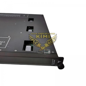
Relay Modules
") The 3500/32M and 3500/33 Relay Modules provide a set of relays that can be programmed to actuate
based on alarm conditions in other monitor modules in the rack. The /32M module (left photo) uses
double pole double throw (DPDT) relays, while the /33 module (right photo) uses single pole double
throw (SPDT) relays. The /32M module has 4 DPDT relay channels and the /33 unit has 16 SPDT
relay channels. The /33 can also be configured to act as if it has DPDT relays. Doing this will use two
SPDT relays to perform the function of every DPDT relay that is configured.
The 3500/32M and 3500/33 Relay Modules provide a set of relays that can be programmed to actuate
based on alarm conditions in other monitor modules in the rack. The /32M module (left photo) uses
double pole double throw (DPDT) relays, while the /33 module (right photo) uses single pole double
throw (SPDT) relays. The /32M module has 4 DPDT relay channels and the /33 unit has 16 SPDT
relay channels. The /33 can also be configured to act as if it has DPDT relays. Doing this will use two
SPDT relays to perform the function of every DPDT relay that is configured.
Although relay modules are not a required component of the 3500 System, we strongly recommend using them as the most appropriate way to integrate the 3500 System with automatic shutdown applications. Any number of relay modules can be placed in any of the slots to the right of the TDI.
3500 System Configuration software facilitates programing “Alarm Drive Logic” that controls relay actuation. This logic can be based on various combinations of alarms, ranging from an individual channel’s Alert, Danger, or NOT OK status to highly complex Boolean expressions that combine two or more channel statuses to provide special AND or OR voting.
By adding the required number of relay modules to the rack, it is possible to provide individual relay contacts for each channel, alarm type, and group of channels for global alarm annunciation.
The 3500 Rack supplies an overall Rack OK relay in addition to any alarm relays in the rack. The Rack OK relay is in the TDI’s I/O module and is connected to the OK circuits of all modules in the rack. These OK circuits monitor the operating condition of each module
Any fault in the module, its transducers, or associated transducer field wiring will be annunciated by the Rack OK relay. This relay is a single-pole, double-throw (SPDT) type and is normally energized, providing added capability of annunciation in the event of primary power loss.
")
Keyphasor Module
The 3500/25 is a half-height module that provides power and termination for up to two Keyphasor
transducers. When applications require one or two Keyphasor transducers, simply install a single
3500/25 module.")
The 3500 System can accommodate up to four Keyphasor transducers per rack by installing two 3500/25 Keyphasor modules in the rack.
When two 3500/25 Keyphasor modules are used, they must be installed in the same rack slot, one above the other.
Keyphasor signals from the 3500/25 module(s) can be routed to appropriate monitor modules via the 3500’s rack backplane for use in speed, phase, tracking filter, and other measurements.
") Communication Gateway
Communication Gateway
Communication Gateway modules allow a 3500 system to digitally transfer selected status and current value data to process control systems, historians, plant computers, and other relevant systems.
The 3500/91 Ethernet Global Data (EGD) Comm Gateway Module accommodates integration with EGD compatible control systems, such as the GE Mark VIe.
The 3500/92 Comm Gateway Module supports Modbus® communication, via serial and Ethernet protocols
Multiple communication gateway modules can be installed in a rack when the system requires redundant communication or must support multiple communication protocols simultaneously
The modules do not interfere with the 3500 System’s normal operations or machinery protection functions, ensuring that the monitoring system integrity is always maintained, even in the unlikely event of a Communication Gateway module failure.
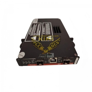
Input/Output (I/O) Modules
") Every module (Monitor, Keyphasor, Power Supply, Communication Processor, etc.) requires a
corresponding I/O module. Main modules connect to the backplane inside the rack, and I/O
modules connect with the other side of the backplane, behind their associated main modules. For
bulkhead-mounted racks, only, each I/O module connects to the face of the backplane above its
associated main module.
Every module (Monitor, Keyphasor, Power Supply, Communication Processor, etc.) requires a
corresponding I/O module. Main modules connect to the backplane inside the rack, and I/O
modules connect with the other side of the backplane, behind their associated main modules. For
bulkhead-mounted racks, only, each I/O module connects to the face of the backplane above its
associated main module.
")
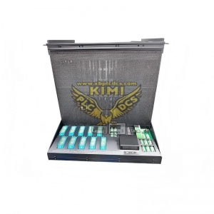
Touch Screen Display
The 3500/94M VGA Display system provides a variety of flexible options, including both a 10” and 15” (diagonal) Touch Screen display.
In addition to the 3500/94M VGA Display Module (left), the display package includes two I/O module choices. The power-only I/O module (middle) is for the 10” Face Mount display, while the standard I/O module (right) is for all other display options
")
Figure 5: 10” Display Face Mount option (upper), 15” Display 19” EIA Rack Mount option (lower)
Intrinsic Safety Barriers or Galvanic_Isolators
For applications where the transducers are installed in a hazardous area, the 3500 System can be used with internal or external intrinsic safety barriers
Internal safety barriers are generally preferred to external barriers because this option saves cost, requires no extra cabinet space, and needs no additional wiring. Internal barriers also improve safety because the connections are pre wired, reducing the possibility for errors introduced by wiring external connections between monitors and barriers.
Internal barriers also improve quality because, unlike external barriers, they require no special monitor scale factor calibration to compensate for voltage drop across the barrier. For additional information, refer to the 3500 Internal Barriers Datasheet, 141495-01.
If galvanic isolators are required to address your specific intrinsic safety requirements, pre-engineered external galvanic isolators and an appropriate housing are available. For additional information, refer to the 3500 Galvanic_Isolator Interface Datasheet, 141714-01.
")
3500 System Configuration Software
This Windows®-based application is used to establish settings for all components of the 3500 Machinery Protection System. These settings are saved in the TDI in a proprietary RAK configuration file.
")
3500 System Configuration Software can be run on a laptop computer, which is connected locally to the USB port on
the face of the TDI, or on a remote computer, which is connected to
the TDI via the plant network. Configuration settings include the following:
Alarm Setpoints
Channel Names
Communication Parameters
Relay Logic
Signal Processing Options
For more information, refer to the 3500 Software datasheet, 141527
Internal and External Terminations
Standard I/O modules accommodate field wiring connections directly to each I/O module. This is the traditional internal termination option. We also offer an External Termination (ET) option that allows field wiring to be landed at ET blocks.
These ET blocks can be mounted where access is more convenient, such as on a cabinet wall, where the field wiring is less congested than when it connects directly to the back of each I/O module.
Each ET block then connects to its monitor’s I/O module using a single pre-engineered cable with multipin connectors, resulting in neater, more easily serviceable installations.
")
")
")
")
using one of the 3500 System’s supported protocols. Hard-wired 4 to 20 mA proportional outputs and relay contacts can be used in lieu of a digital interface to older control or automation systems. l A VGA Touch Screen Display can be mounted at the rack location, or remotely, for display of data, system status, and alarm events. l System 1 Condition Monitoring and Diagnostic software enables full Machinery Management functionality. Refer to www.bently.com for details. Specifications and Ordering Information
Specifications and Ordering Information
Sales Manager: Li Ming
WeChat: 18059884790
WHATSAPP:+86 18059884790
Email:plc66@qq.com
Graphs and Figures
This graphical reference section includes additional information about the 3500 System.
3500 System Example
")
1. Power Supplies: This particular rack has an AC-powered supply in the primary (lower) position, and a DC-powered backup supply in the upper position.
2. Keylock security prevents tampering with the configuration of the monitors in the rack.
3. Transient Data Interface (TDI): Provides an interface to configuration software and to System 1 Condition Monitoring & Diagnostic software. It also coordinates communication between all modules in the rack.
4. Keyphasor Module: Accepts single and multi-event per-rotation signals from proximity probes and magnetic pickups installed on rotating equipment.
5. 3500/72M (Recip Rod Position) and 3500/77M (Recip Cylinder Pressure) monitors are used for condition monitoring of reciprocating compressors.
6. 60/61 Temperature Monitors.
7. 3500/42M Proximitor/Seismic vibration monitors.
8. Buffered transducer signals are provided for use with portable test instruments.
9. Unused slots are protected with “Future Expansion” covers, and are available for use with additional modules.
10. 3500/33 16-Channel Relay Module. 11. 3500/92 Modbus® Communication Gateway. 12. Standard rack for 19” EIA rail mounting
3500/94M VGA Display Options
This overview shows the various components that make up the 3500/94M VGA Display options. For detailed information, refer to the associated datasheet, 122M3217.
")
")