

News
Featured
Contact Us
Contact: POWER DUKE
Phone: +86 18059884790
E-mail: plc66@qq.com
Add: fujian xiamen
- Warehouse: Spot
- Warranty: 365 days
- Quality: Original module
- Condition: New
- Shipping method: Courier delivery
- Contact person: LI MING
- Contact number: +86 18059884790
- WeChat:18059884790
- E-mail: plc66@qq.com
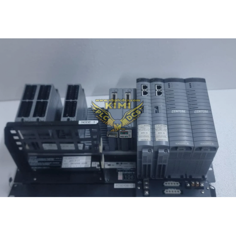
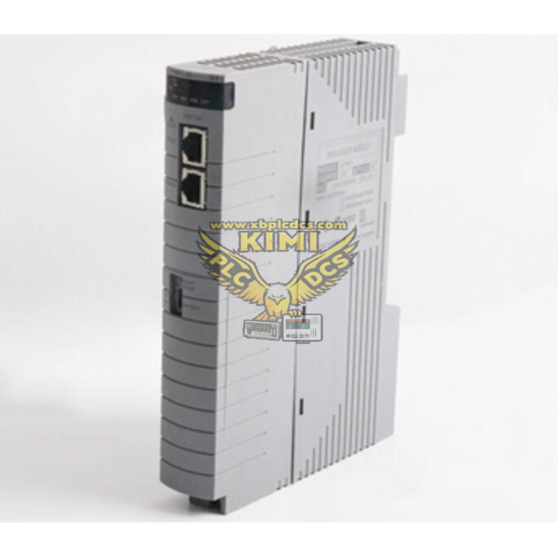
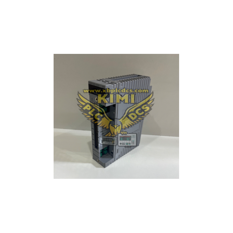
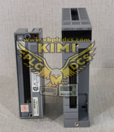
## Product Model: YOKOGAWA AAT141‑S00 S2, 16‑Channel Isolated TC/mV Analog Input Module (CENTUM‑VP DCS) ```
1. Product Description
AAT141‑S00 S2 is a high‑precision hot‑swappable temperature and millivolt analog‑input module developed by Yokogawa for the CENTUM‑VP distributed‑control‑system platform. It provides 16 fully‑galvanic‑isolated input channels, each channel can be independently configured to receive thermocouple signals (J, K, E, B, R, S, T, N) or low‑level millivolt signals (-100~150mV, -20~80mV) from field sensors. With built‑in cold‑junction compensation, burnout detection, high‑resolution A/D conversion circuits and 1500V AC channel‑to‑system isolation protection, it effectively suppresses ground‑loop interference. The S2 revision version adopts pressure‑clamp terminal connection interface, communicates with the FCS controller via ESB back‑plane bus, supports dual‑redundant rack installation, and can run continuously and stably within -20℃~+70℃ for long‑term unattended temperature‑monitoring tasks in process‑industry control cabinets.
2. Core Product Functions
- Collect thermocouple temperature signals and millivolt weak‑voltage signals from field temperature‑measuring sensors
- Convert low‑level analog mV signals into high‑precision digital temperature‑data readable by DCS controllers
- Built‑in automatic cold‑junction compensation to eliminate temperature‑measurement error at cabinet‑side terminals
- Independent galvanic isolation for every channel to block electromagnetic noise and prevent surge damage to DCS rack hardware
- Burn‑out detection function, triggering an alarm when thermocouple sensor wires break off
- Support hot‑swap replacement and dual‑redundant configuration to avoid process interruption during module maintenance
- Real‑time self‑diagnosis for channel open‑circuit, over‑range input, back‑plane communication and power‑supply faults
- Upload real‑time temperature‑sampling values and fault‑alarm information to operator HMI and upper SCADA monitoring system
3. Application Scenarios
- Thermal‑power‑plant boiler furnace, superheater and steam‑turbine metal‑wall temperature monitoring DCS racks
- Petrochemical refinery heating‑furnace, reactor and distillation‑column multi‑point temperature‑acquisition cabinets
- Chemical plant high‑temperature reaction‑kettle, heat‑exchanger and pipeline temperature‑monitoring control panels
- Metallurgical sintering‑furnace, cement rotary‑kiln and glass‑furnace multi‑point temperature‑measurement stations
- Waste‑incineration‑power‑generation flue‑gas and combustion‑chamber temperature‑data‑collection control cabinets
- Food‑processing and pharmaceutical‑industry high‑temperature sterilization‑process closed‑loop temperature‑monitoring nodes
4. Common Problems & Troubleshooting
Q1: DCS system cannot identify AAT141‑S00 S2 module after rack power‑on
A: Power‑off the DCS rack, pull out and fully re‑seat the module; clean oxidized gold‑finger contacts on ESB‑bus back‑plane slots; inspect stable 24VDC auxiliary‑power‑supply output.
Q2: Temperature‑measurement values drift, fluctuate or display abnormal offset during operation
A: Verify total resistance of thermocouple wiring does not exceed 1000Ω; use shielded thermocouple compensation‑cables; separate temperature‑signal cables from high‑power power‑lines; check cold‑junction‑compensation parameter settings in DCS configuration software.
Q3: DCS reports sensor burnout fault while the thermocouple sensor is physically intact
A: Retighten pressure‑clamp terminal screws; clean oxide on compensation‑wire metal contacts; check aging or high‑resistance joints in long‑distance extension cables.
Q4: Single‑channel temperature reading remains fixed and fails to respond to actual‑temperature changes on‑site
A: Swap thermocouple wiring to a spare normal channel to confirm internal module hardware failure; re‑download and activate channel‑type configuration parameters (TC‑type or mV‑input) in the DCS engineering tool.
Q5: Redundant primary‑standby module switch‑over failure triggers temporary temperature‑data‑loss alarm
A: Confirm identical channel‑configuration parameters for main and standby modules; clean ESB‑bus back‑plane communication contacts; inspect loose internal inter‑module connection cables inside the DCS rack.
```