

News
Featured
Contact Us
Contact: POWER DUKE
Phone: +86 18059884790
E-mail: plc66@qq.com
Add: fujian xiamen
- Warehouse: Spot
- Warranty: 365 days
- Quality: Original module
- Condition: New
- Shipping method: Courier delivery
- Contact person: LI MING
- Contact number: +86 18059884790
- WeChat:18059884790
- E-mail: plc66@qq.com
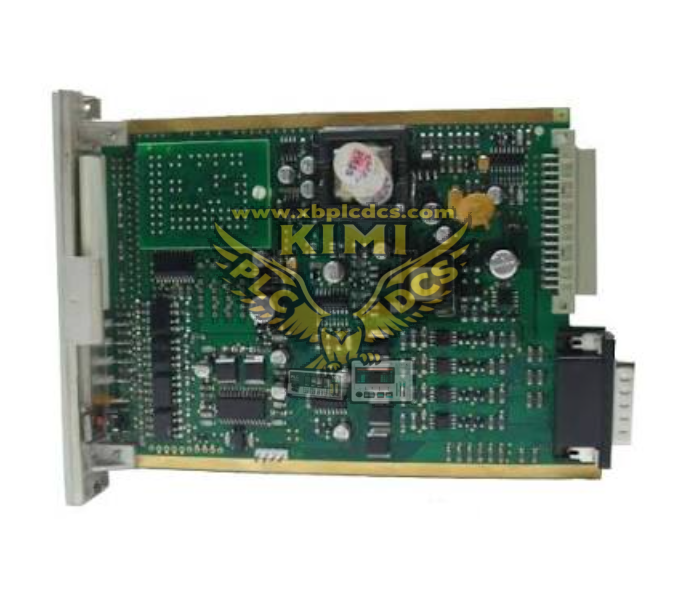
Honeywell 05704‑A‑0145 4‑Channel Gas Detection Control Card (System 57 Platform)
1. Product Description
05704‑A‑0145 is a rack‑mounted four‑channel control card exclusively for Honeywell System 57 industrial gas safety monitoring rack system. It is dedicated to collecting 4–20mA analog signals from flammable, toxic and oxygen gas detectors, integrating signal conditioning, concentration calculation, multi‑level alarm judgment and loop fault diagnosis functions. This half‑width plug‑in board works with System 57 engineering card, relay output card and alarm interface card to build a complete fire & gas (F&G) safety system. Each channel provides isolated 24VDC loop power supply for 2‑wire gas transmitters, with built‑in short/open circuit protection for field sensor loops. Standard front panel LED status indicators display channel running, pre‑alarm, main alarm and hardware fault status. Core electrical specs: Max power consumption 8.3W (typical 7.5W); isolated 24V±5% loop power, max 25mA per channel; signal measurement range 0–25mA; max field loop resistance 500Ω; operating temperature 0℃ ~ +70℃, storage -40℃ ~ +85℃, CE certified, industrial safety grade design.
2. Core Product Functions
- 4 independent 4–20mA input channels: Simultaneously receive signals from 4 gas detectors (methane, CO, H2S, O2, VOC etc.), linear conversion to gas concentration readings.
- Isolated loop power supply: Each channel supplies regulated 24V power to field 2‑wire gas transmitters, galvanic isolation eliminates ground loop interference.
- Multi‑threshold alarm logic: Supports A1 pre‑alarm, A2 main alarm, A3 high hazard trip; toxic gas mode adds STEL/LTEL cumulative exposure alarm calculation.
- Full loop fault self‑diagnosis: Real‑time detection of sensor open circuit, short circuit, overvoltage; fault signals output to rack relay cards for alarm interlock.
- Calibration support: Zero/span calibration for each channel via System 57 engineering card, store calibration parameters on‑board non‑volatile memory.
- Remote control interface: Accept remote alarm reset, channel inhibit interlock signals from DCS/PLC; rack bus realizes system unified alarm acknowledge.
- Hierarchical alarm output linkage: Channel alarms drive rack relay cards to trigger site sirens, shutdown valves, fire suppression equipment; global master alarm aggregation logic supported.
- Backplane rack communication: Exchange real‑time gas concentration, alarm status and fault codes with System 57 rack main bus for upper monitoring system upload.
- Hot‑swap compatible: Supports online replacement in powered System 57 rack without full cabinet shutdown, minimizes safety monitoring downtime.
3. Typical Application Scenarios
- Oil & gas offshore platforms & refineries: F&G safety rack for process area combustible and toxic gas leakage monitoring, ESD interlock trigger.
- Petrochemical chemical plants: Reactor, tank farm, pump room gas detection, toxic gas exposure personnel safety monitoring.
- Thermal power plants: Boiler room hydrogen, CO, flammable gas monitoring for turbine and auxiliary workshop safety.
- Mining & metallurgy: Underground tunnel and smelting workshop toxic gas monitoring safety systems.
- Pharmaceutical & chemical manufacturing: Explosion‑proof production workshop solvent vapor concentration detection and alarm control.
- Water treatment plants: Sewage tank, chemical dosing room toxic gas monitoring and ventilation interlock control.
4. Common Faults & Troubleshooting Issues
4.1 Module Not Recognized by System 57 Rack
Symptom: All channel LEDs off, engineering card displays "Card Missing". Root causes: Poor backplane gold pin contact, incomplete module insertion, rack power supply undervoltage, corrupted onboard firmware. Solution: Power off rack, fully reseat module and lock fixing latches, clean backplane contact pins, verify rack 24VDC power rail voltage, reflash firmware via engineering card.
4.2 Single Channel Fixed Zero Reading / Loop Fault Alarm
Symptom: One channel fault LED lit, gas concentration always zero or maximum overrange. Root causes: Broken sensor cable, shorted field wiring, damaged gas transmitter, internal channel signal conditioning circuit burnout. Solution: Disconnect field wiring to test channel output, inspect cable continuity, replace faulty gas detector, swap spare 05704‑A‑0145 to confirm hardware failure.
4.3 False Continuous Alarm Without Actual Gas Leakage
Symptom: Channel A2/A3 alarm triggers constantly with clean air environment. Root causes: Drifted sensor calibration parameters, improper alarm threshold setting, strong electromagnetic interference near signal cables, damaged sensor membrane. Solution: Perform full zero/span calibration via engineering card, adjust alarm limit values, re‑route shielded signal cables away from high‑power motors and inverters, replace aging gas detector sensor head.
4.4 Loop Power Supply Overload Fault
Symptom: Channel power fault indicator on, transmitter cannot power up normally. Root causes: Field wiring short circuit, multiple sensors connected to single channel exceeding 25mA current limit, internal power regulator damage. Solution: Isolate field wiring to eliminate short circuit, reassign sensors to separate channels to reduce load current, replace control card if power circuit damaged.
4.5 Hot‑Swap Triggers Unplanned System Master Alarm
Symptom: Global safety alarm activates during online card replacement. Root causes: Improper extraction/insertion angle, dust oxidation on backplane contact fingers, damaged backplane isolation circuit. Solution: Power down rack before maintenance to clean gold pins, strictly follow Honeywell System 57 hot‑swap operation manual, inspect rack backplane for bent pins and damaged isolation circuits.
4.6 Module Overheating & Intermittent Channel Signal Drift
Symptom: Circuit board surface hot, gas reading fluctuates randomly, occasional self‑reset. Root causes: Cabinet ventilation blocked, ambient temperature exceeds 70℃, dust accumulation on PCB heat dissipation components, long‑term full four‑channel heavy load operation. Solution: Clean cabinet air filter and ventilation slots, install auxiliary cooling fans, remove dust deposits on module circuit board, distribute high‑load sensors across multiple control cards to reduce single card load.