

News
Featured



Contact Us
Contact: POWER DUKE
Phone: +86 18059884790
E-mail: plc66@qq.com
Add: fujian xiamen
- Warehouse: Spot
- Warranty: 365 days
- Quality: Original module
- Condition: New
- Shipping method: Courier delivery
- Contact person: LI MING
- Contact number: +86 18059884790
- WeChat:18059884790
- E-mail: plc66@qq.com
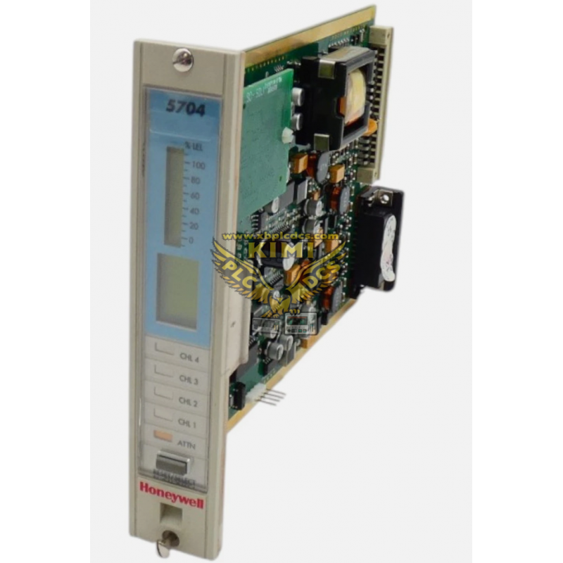
Honeywell 05704-A-0145 4-20mA Four Channel Gas Detection Control Card (System 57 Series)
1. Product Description
05704-A-0145 is a rack-mount 4-channel gas detection control card developed by Honeywell Analytics for the System 57 Fire & Gas (F&G) safety control platform, specifically designed to interface with 4-20mA loop-powered gas transmitters (distinguished from catalytic sensor variant 05704-A-0144).
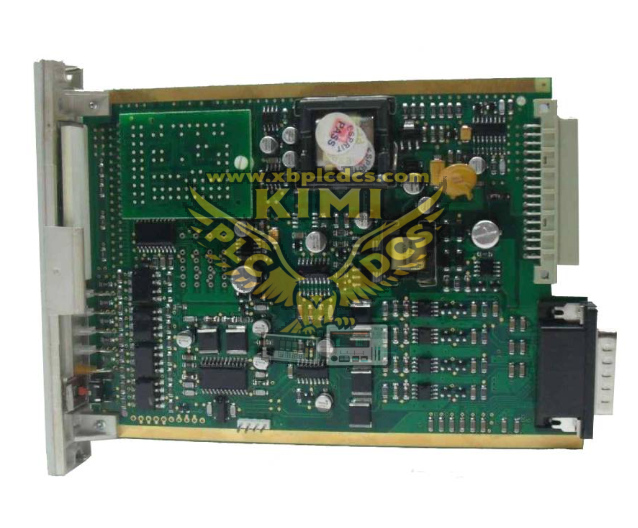
This standard 3U Eurocard pluggable module fits into System 57 rack slots, supporting hot-swap maintenance without shutting down the whole gas monitoring system. It adopts microprocessor-based signal processing with EEPROM storage for site configuration parameters, and features a front panel LCD display, multi-color alarm LED indicators and physical reset pushbutton for local operation and status viewing.
Basic electrical specifications: 24VDC rack auxiliary power supply, four isolated 4-20mA analog input channels, built-in signal surge suppression circuit, operating temperature range 0°C ~ +55°C, conformal coated PCB for anti-dust and moisture protection, CE and ATEX industrial safety compliance. Each card can independently monitor four separate hazardous zones, and communicate with the rack engineering card and relay output modules to realize gas concentration alarm and safety interlock logic.
2. Core Product Functions
- 4-Channel 4-20mA Analog Signal Acquisition Collect real-time gas concentration signals from toxic, flammable or oxygen deficiency transmitters across four independent monitoring zones, with built-in signal filtering to eliminate field transmission noise interference.
- Multi-Stage Gas Alarm Judgment Logic Configurable low pre-alarm and high critical alarm thresholds for each channel; trigger front panel LED visual alarms and transmit alarm signals to rack relay modules for site horn, strobe light or equipment shutdown interlock.
- Local HMI Display & Manual Operation Front panel backlit LCD sequentially shows each channel’s gas reading, channel number and fault status; physical pushbutton supports alarm reset, channel switching and local parameter viewing without external software.
- Comprehensive Channel Self-Diagnosis Continuously monitor sensor wire open-circuit, short-circuit, loop power loss and internal card hardware faults; lock alarm output and log fault codes when abnormal circuit conditions are detected.
- Hot-Swap Maintenance Support Modular plug-in structure allows single card replacement while other System 57 rack channels remain operational, avoiding full gas monitoring system outage during maintenance.
- Expansion Analog Output Interface Reserved onboard slots for optional plug-in analog output sub-modules, providing isolated 4-20mA remote signal transmission to DCS/PLC host systems for centralized plant monitoring.
- Persistent Configuration Storage All alarm threshold, sensor type and communication settings stored in on-board EEPROM; configuration data remains intact after power cycle without repeated re-setup.
- Isolated Signal Circuit Design Galvanic isolation between field sensor loops and rack internal bus, prevents ground loop interference from high-power industrial equipment and protects the core control circuit from surge damage.
3. Typical Application Scenarios
- Oil & Gas Offshore Platforms & Onshore Refineries Monitor flammable methane, hydrogen sulfide toxic gas concentrations in process areas, pump rooms and compressor buildings to trigger emergency ventilation and equipment trip interlocks.
- Chemical & Petrochemical Production Plants Multi-zone gas safety monitoring for reactor workshops, chemical storage tank farms and waste gas treatment stations, preventing explosion and toxic gas leakage hazards.
- Thermal Power Plant Auxiliary Buildings Hydrogen detection for generator room battery compartments, fuel gas monitoring for boiler burner areas, oxygen deficiency supervision for closed underground cable tunnels.
- Mining & Metallurgical Facilities Underground mine toxic and flammable gas monitoring, furnace workshop fuel gas leak detection, coordinated with ventilation fan safety interlock control.
- Pharmaceutical & Laboratory Factories Volatile organic solvent (VOC) gas monitoring in reagent storage rooms and synthesis workshops, low-concentration toxic gas early warning for personnel safety protection.
- LNG & Natural Gas Distribution Stations Pipeline valve chamber, compressor station and gas storage tank area leakage monitoring, automatic gas shut-off valve interlock upon high-concentration alarm.
- Industrial Wastewater Treatment Plants Hydrogen sulfide gas monitoring in sewage tank rooms and sludge treatment workshops, linkage control of exhaust fans and toxic gas exhaust systems.
4. Common Faults & Troubleshooting Issues
4.1 Single Channel Fault Alarm, LCD Shows "Loop Fault"
Causes: Broken sensor 4-20mA wiring, corroded terminal block contacts, faulty gas transmitter loop power circuit, short-circuit between signal wire and ground. Solution: Power off the rack to inspect field sensor cable continuity; clean and re-tighten card wiring terminals; test transmitter loop voltage; replace damaged gas detector if hardware failure occurs.
4.2 False High Gas Concentration Alarm Without Actual Gas Leakage
Causes: Unshielded sensor cables running parallel with high-power power cables causing EMI noise, incorrect alarm threshold parameter settings, sensor drift aging, unstable 24VDC loop supply voltage. Solution: Separate power and signal cable routing with shield grounding; recalibrate alarm limit values via System 57 engineering card; perform sensor zero calibration or replace aging transmitters.
4.3 Card Not Recognized by System 57 Rack Engineering Card
Causes: Poor contact between card edge gold fingers and rack backplane slot, insufficient rack 24VDC power supply, corrupted EEPROM configuration data, internal main processing chip failure. Solution: Hot-swap the card after cleaning edge connector gold fingers; verify rack power rail voltage; restore factory default configuration and re-download parameters; replace 05704-A-0145 if communication circuit damaged.
4.4 Front Panel LCD Blank, No LED Status Indication
Causes: Loss of rack auxiliary power supply to the slot, damaged onboard power conversion circuit, loose internal display wiring connector on the PCB. Solution: Check rack slot fuse and 24V bus power; inspect card internal power circuit components; re-seat LCD flat cable connector on the control board.
4.5 Alarm Reset Button Unresponsive, Alarm Status Cannot Be Cleared
Causes: Stuck mechanical pushbutton switch on front panel, persistent gas concentration exceeding alarm threshold, internal logic latch circuit fault. Solution: Confirm gas concentration has returned to safe range; clean or replace faulty reset pushbutton; power cycle the card to reset internal alarm latch logic.
4.6 Intermittent Unstable Gas Concentration Readings
Causes: Loose wiring terminals, degraded PCB conformal coating causing conductive dust accumulation, cabinet cooling fan failure leading to card overheating, long-distance sensor cable signal attenuation. Solution: Re-tighten all terminal wiring; clean dust deposits on PCB surface; improve cabinet ventilation; add signal repeater for ultra-long sensor wiring runs.
4.7 Analog Output Expansion Module Fails to Transmit Signals to DCS
Causes: Poor contact between expansion sub-module and main card slot, incorrect analog output range configuration, short-circuit of remote DCS receiving circuit. Solution: Re-seat the analog output expansion module; reconfigure 4-20mA output range parameters; isolate and inspect DCS receiving loop wiring.