

News
Featured
Contact Us
Contact: POWER DUKE
Phone: +86 18059884790
E-mail: plc66@qq.com
Add: fujian xiamen
- Warehouse: Spot
- Warranty: 365 days
- Quality: Original module
- Condition: New
- Shipping method: Courier delivery
- Contact person: LI MING
- Contact number: +86 18059884790
- WeChat:18059884790
- E-mail: plc66@qq.com
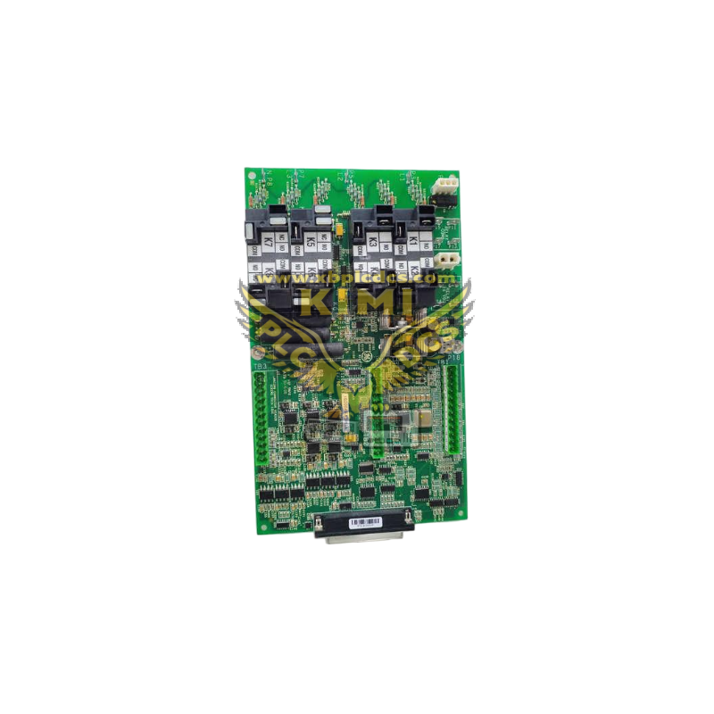
Honeywell 05704-A-0121 Quad Relay Interface Card (System 57 Fire & Gas Platform)
1. Product Description
05704-A-0121 is a 3U rack-mount quad relay output interface module exclusively designed for Honeywell System 57 fire and gas safety control racks, serving as the power drive bridge between System 57 gas control cards (such as 05704-A-0145) and field high-power safety equipment.
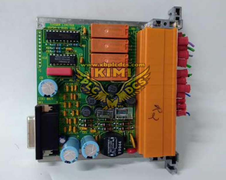
This single-slot pluggable card integrates four independent SPCO (Single Pole Change Over) relay channels, each rated for 5A resistive load at 250VAC / 32VDC. It receives low-voltage logic alarm signals from upstream gas detection control cards and converts them into isolated high-current dry contact outputs to actuate external safety devices. The module supports hot-swap replacement without shutting down the entire rack, with conformal coated PCB to resist dust, humidity and corrosive gas inside industrial control cabinets.
Core electrical parameters: 18~32VDC rack auxiliary power supply, max power consumption 1.7W, operating temperature range -5°C ~ +55°C, terminal blocks accept 14AWG (2.5mm²) field wiring. It is fully compatible with all 05704 series gas input control cards, and works with System 57 engineering cards to configure relay trigger modes (latching / non-latching, energized / de-energized alarm state).
Key difference from 05704-A-0145: 05704-A-0145 is the signal acquisition control card for 4-20mA gas detectors, while 05704-A-0121 is the relay expansion output card responsible for executing safety interlock actions.
2. Core Product Functions
- 4 Independent Isolated Relay Output Channels Four separate SPCO relay circuits provide isolated dry contact signals to drive external loads including alarm horns, strobe lights, ventilation fans, emergency shut-off valves and pump interlock circuits; each channel operates independently without cross-channel interference.
- Configurable Relay Trigger Logic Via System 57 engineering software, users set relay working modes: latching/non-latching, energized-on-alarm or de-energized-on-alarm, matching SIL safety requirements for different industrial hazard zones.
- Multi-Stage Alarm Linkage Execution Receives pre-alarm, critical gas alarm and system fault signals from upstream gas control cards; each relay channel can be bound to specific alarm thresholds to realize graded safety response logic.
- Comprehensive Circuit Self-Monitoring Continuously detect internal relay coil failure, rack power undervoltage and backplane communication loss; transmit fault diagnostic codes to the rack master engineering card for HMI alarm display.
- Hot-Swap Maintenance Support Modular Eurocard design allows single card removal/replacement while other gas monitoring and relay channels remain operational, eliminating full safety system shutdown during maintenance work.
- Galvanic Isolation Protection Optocoupler isolation between rack low-voltage logic bus and field high-power relay contact circuits, preventing ground loop surge damage to core gas detection control hardware.
- Persistent Parameter Storage Relay mode configuration parameters stored in on-board non-volatile memory; settings remain intact after power cycle without repeated reconfiguration.
- Rack System Expansion Multiple 05704-A-0121 cards can be installed in one 19-inch System 57 rack to expand dozens of safety interlock output channels for large multi-zone gas monitoring systems.
3. Typical Application Scenarios
- Oil & Gas Refineries and Offshore Platforms Trigger emergency gas shut-off valves, exhaust ventilation fans and site audible/visual alarms when H₂S or methane leakage is detected; interlock with compressor trip circuits.
- Chemical & Petrochemical Plants Multi-zone toxic/flammable gas safety interlock control for reactor buildings, chemical tank farms and waste gas treatment workshops; graded alarm activation for different hazard levels.
- Thermal Power Plant Auxiliary Buildings Hydrogen leak detection interlock for generator battery rooms, fuel gas alarm linkage for boiler burner facilities, oxygen deficiency ventilation fan control for underground cable tunnels.
- LNG & Natural Gas Compressor Stations Drive pipeline emergency cut-off valves and site evacuation alarms upon high-concentration gas detection, coordinate with station DCS system via relay dry contacts.
- Pharmaceutical & Laboratory Manufacturing VOC solvent gas monitoring interlock control, automatic exhaust fan startup and equipment power cut-off for reagent storage and synthesis workshops.
- Mining & Metallurgical Factories Underground mine toxic gas alarm actuation, furnace fuel gas leakage interlock control for high-temperature production workshops.
- Industrial Wastewater Treatment Plants Hydrogen sulfide gas monitoring linkage control for sewage tank rooms, automatic exhaust equipment startup and staff safety alert triggers.
4. Common Faults & Troubleshooting Issues
4.1 Relay Channel Fails to Actuate Load on Alarm Trigger
Causes: Relay contact burnout from overcurrent load, mismatched relay trigger mode configuration, broken backplane signal wiring, loose field terminal block connections. Solution: Disconnect external high-power load to test relay contact integrity; reconfigure latching/energized alarm logic via engineering software; re-tighten rack backplane and field wiring terminals; replace the card if internal relay coil is damaged.
4.2 System Rack Reports Interface Card Communication Fault
Causes: Poor contact between card gold fingers and rack backplane slot, rack 24VDC auxiliary power undervoltage, corrupted onboard configuration data, damaged backplane communication circuit. Solution: Power off the rack, extract and clean the card edge connector gold fingers; verify rack slot power rail voltage; restore factory default settings and re-download relay parameters; replace 05704-A-0121 if communication circuit failure is confirmed.
4.3 Relay Stuck Latching, Cannot Reset Alarm Status Automatically
Causes: Latching relay mode enabled without remote reset signal, relay mechanical contact welding, continuous gas alarm signal input from control card. Solution: Switch relay to non-latching mode in engineering configuration; cut off load power to release welded contacts; eliminate the root gas leakage fault to clear upstream alarm signal.
4.4 Intermittent Relay Chattering & Unstable Load Operation
Causes: Unstable rack DC power supply, electromagnetic interference from adjacent high-power power modules, loose wiring terminals causing signal fluctuation, PCB dust accumulation causing partial short circuit. Solution: Stabilize rack auxiliary power output; separate signal rack from high-current power cabinets; clean PCB dust deposits and re-tighten all wiring terminals.
4.5 Relay Contact Burnout After Short-Term Operation
Causes: External field load exceeds 5A rated contact current, inductive loads (solenoid valves, motors) without surge suppression diodes, long-term continuous energized relay operation. Solution: Add external relay amplifiers for heavy loads; install freewheeling diodes across inductive equipment terminals; adjust relay duty cycle to reduce continuous energized time.
4.6 Hot-Swap Replacement Causes Temporary All Relay Output Trigger
Causes: Rack backplane bus transient voltage spike during card insertion, missing card insertion anti-surge protection circuit. Solution: Follow official hot-swap operation sequence (disable alarm logic first before extraction); install rack bus surge suppression modules to eliminate transient voltage interference.