

Product
Product
News
Featured
Contact Us
Contact: POWER DUKE
Phone: +86 18059884790
E-mail: plc66@qq.com
Add: fujian xiamen
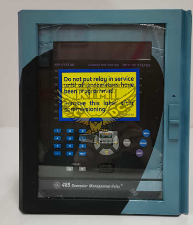
GE Multilin SR489‑P5‑LO‑A20‑E Generator Management Relay
- Warehouse: Spot
- Warranty: 365 days
- Quality: Original module
- Condition: New
- Shipping method: Courier delivery
- Contact person: LI MING
- Contact number: +86 18059884790
- WeChat:18059884790
- E-mail: plc66@qq.com
Product Description
GE Multilin SR489‑P5‑LO‑A20‑E Generator Management Relay
Product Description
The SR489‑P5‑LO‑A20‑E belongs to GE Multilin 489 series, it is a panel‑mounted multifunction generator management and protection relay for synchronous and induction generators. The suffix "LO" indicates low auxiliary power supply range (24‑60 V DC / 24‑60 V AC). This unit receives CT and PT secondary signals, integrates full‑set ANSI‑compliant protection elements, high‑accuracy metering, local HMI, configurable I/O and multi‑port communication. It supports disturbance oscillography, sequence‑of‑event logging, and works with Enervista 489PC configuration software for setup, diagnostics and firmware upgrade.
Product Features
- Comprehensive generator ANSI protection: overcurrent, negative sequence, reverse power, loss‑of‑excitation, over‑/under‑voltage, over‑/under‑frequency, stator earth‑fault protection
- High‑precision metering for three‑phase current, voltage, active/reactive power, power factor and energy values
- Local graphic LCD display and keypad for on‑site checking, parameter setting and fault review
- Configurable 7 digital inputs, multiple relay trip/alarm outputs and 4‑20 mA analog output channels
- Built‑in breaker failure supervision, VT fuse failure detection and CT shorting function for maintenance safety
- Event log, SOE timestamp records and fault oscillography for post‑incident root‑cause analysis
- Communication interfaces: RS485, Ethernet; supports Modbus RTU/TCP, DNP3.0, IEC‑60870‑103 protocols
- Low auxiliary power: 24‑60 V DC / 24‑60 V AC, suitable for substation battery‑bank power supply
- Programmable custom logic for interlock, alarm and breaker control sequences
- Draw‑out plug‑in chassis for convenient replacement without rewiring field terminals
Application Scenarios
- Protection and control for industrial synchronous generator sets and cogeneration units
- Backup generator protection for factories, hospitals and large‑size data centers
- Small‑medium hydro‑power and distributed generation generator supervision
- Marine and offshore platform generator set protection system
- Generator breaker control cabinet in power‑plant auxiliary systems
- Field protection device connecting to SCADA / DCS remote monitoring platforms
Common Problems & Troubleshooting
- No front‑panel display: Check 24‑60 V DC/AC auxiliary power supply voltage and polarity; inspect cabinet fuse and terminal torque.
- Incorrect metering readings: Verify CT/PT secondary wiring and short‑circuit risk; confirm CT/PT ratio parameters match actual instrument transformers.
- Unintended trip or false alarm: Re‑examine protection setting values; check external DI interlock signals; download oscillography file to confirm real fault trigger source.
- Communication link failure: Inspect RS485 or Ethernet cable; match device address, baud‑rate and protocol; eliminate ground‑loop interference on communication wiring.
- Configuration upload/download failure: Check PC‑relay physical connection; ensure Enervista software and relay firmware version compatibility; remove write‑protection lock.
- Breaker cannot be controlled locally or remotely: Check DI/DO wiring status; verify control permission settings; inspect breaker auxiliary contact and trip‑coil circuit.
- Relay self‑diagnostic fault alarm: Perform full power‑cycle reset; check cabinet ambient temperature and ventilation; replace relay if persistent self‑test error occurs.
Related recommendations