
News
Featured
Contact Us
Contact: POWER DUKE
Phone: +86 18059884790
E-mail: plc66@qq.com
Add: fujian xiamen
- Warehouse: Spot
- Warranty: 365 days
- Quality: Original module
- Condition: New
- Shipping method: Courier delivery
- Contact person: LI MING
- Contact number: +86 18059884790
- WeChat:18059884790
- E-mail: plc66@qq.com
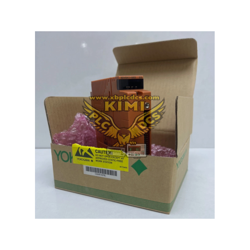
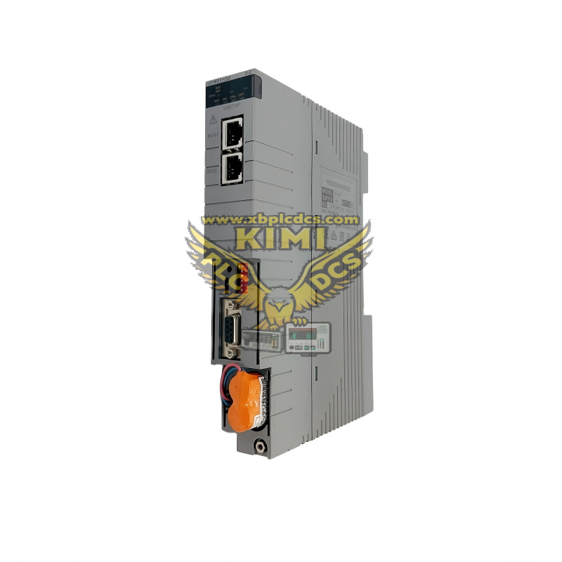
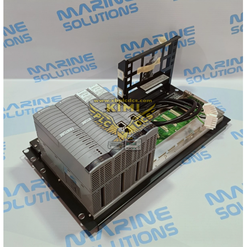
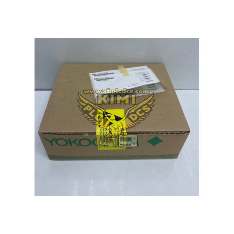
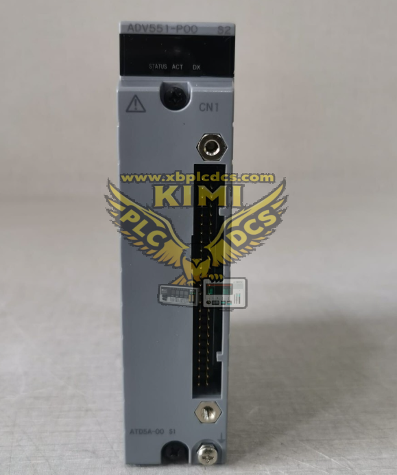
Product Model: YOKOGAWA ADV551‑P00 S2, 32‑Channel Isolated 24VDC Digital Output Module (CENTUM‑VP DCS‑FIO)
1. Product Description
ADV551‑P00 S2 is a high‑density hot‑swappable digital output module developed by Yokogawa for the CENTUM‑VP distributed‑control‑system FIO field‑I/O platform. It provides 32 isolated transistor‑sink output channels rated for 24 VDC field‑side signals, with each channel supporting a maximum load current of 50 mA. The‑P suffix enables pulse‑width‑modulation and time‑proportional output functions, while S2 stands for the latest hardware revision with pressure‑clamp terminal interface. Built‑in channel‑to‑system galvanic isolation, short‑circuit and over‑current protection circuits prevent surge damage to the DCS back‑plane. Communicating with the FCS controller via the ESB bus, this module supports dual‑redundant hot‑standby configuration, and is designed for stable 24‑hour continuous operation within ‑20℃ ~ +70℃ in process‑industry control cabinets.
2. Core Product Functions
- Convert digital on‑off control commands from the DCS controller into 24 VDC transistor‑switch output signals
- Drive field‑side devices including solenoid valves, auxiliary relays, indicator lamps and motor starter interlock circuits
- Three configurable output modes: status switch‑output, pulse output, and time‑proportional PWM output
- Independent galvanic isolation for each channel to isolate field‑side electrical interference and protect DCS hardware
- Built‑in hardware over‑current and short‑circuit protection for fault‑tolerant operation on individual output loops
- Support hot‑swap replacement and dual‑redundant installation for non‑stop operation during online maintenance
- Real‑time self‑diagnosis for output overload, back‑plane communication failure and module power‑supply faults
- Upload channel status and fault‑alarm messages to operator HMI workstation and upper‑level SCADA monitoring system
3. Application Scenarios
- Petrochemical refining‑plant shutdown interlock, switching‑valve and pump‑start‑stop DCS control cabinets
- Thermal‑power‑plant boiler burner ignition, damper actuator and turbine auxiliary‑equipment interlock racks
- Chemical‑factory reactor safety interlock, feeding‑valve switching and alarm‑indicator‑light control panels
- Municipal water‑supply and sewage‑treatment‑plant pump‑group, aeration‑valve and sludge‑valve control stations
- Natural‑gas compressor‑station anti‑surge bypass‑valve, emergency‑shutdown and local alarm‑signal systems
- Metallurgy, cement and waste‑incineration‑plant production‑line sequential‑logic and safety‑interlock DCS nodes
4. Common Problems & Troubleshooting
Q1: DCS cannot detect ADV551‑P00 S2 module after rack power‑on
A: Power‑off the DCS node rack, pull out and fully re‑seat the module; clean oxidized gold‑finger contacts on the ESB‑bus back‑plane slot; verify stable 24VDC auxiliary‑power‑supply output.
Q2: Output channel shows ON state in DCS but the field actuator fails to actuate
A: Check external 24VDC field‑side power supply; measure actual output voltage at module terminals; inspect loose pressure‑clamp wiring terminals and open‑circuit faults on field cables.
Q3: System repeatedly triggers channel over‑current or short‑circuit alarm
A: Disconnect field wiring to isolate short‑circuited loops; confirm field‑side load current does not exceed the 50 mA per‑channel rating; replace burnt‑out output channel if internal hardware damage occurs.
Q4: Pulse‑width‑modulation output does not respond to DCS parameter adjustments
A: Swap field wiring to a spare healthy output channel to confirm hardware failure; re‑download and activate channel‑function configuration parameters inside the DCS engineering tool.
Q5: Redundant primary‑standby module switch‑over failure causes temporary loss of digital‑output control
A: Confirm identical channel‑configuration parameters for both main and standby modules; clean ESB‑bus back‑plane communication contacts; inspect loose internal inter‑module connection cables inside the DCS rack.
```