

News
Featured
Contact Us
Contact: POWER DUKE
Phone: +86 18059884790
E-mail: plc66@qq.com
Add: fujian xiamen
- Warehouse: Spot
- Warranty: 365 days
- Quality: Original module
- Condition: New
- Shipping method: Courier delivery
- Contact person: LI MING
- Contact number: +86 18059884790
- WeChat:18059884790
- E-mail: plc66@qq.com
GE Vernova GFM252 Fixed Time-Delay Ground Fault Monitor Relay Document
1. Product Description
GFM252 (also marked GFM-252) is a Class 1 self-powered ground fault monitoring relay manufactured by GE Vernova, designed for polyphase industrial power systems to detect destructive arcing ground faults and protect motors, MCCs and switchgear equipment.
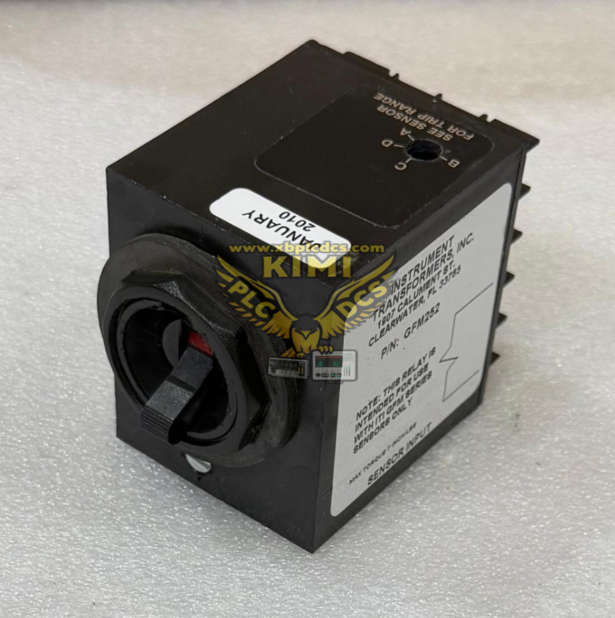
This relay works paired with dedicated GFM zero-sequence current sensors to capture residual ground fault current. It features four continuous adjustable pickup ranges (A to D, A=lowest trip current, D=highest) for flexible coordination with upstream/downstream protection devices. Unlike adjustable-delay variants such as GFM262, GFM252 adopts a fixed inverse time trip characteristic without field-configurable time delay settings; maximum trip time may exceed 1 second at the minimum pickup threshold, while response accelerates sharply under high fault current (as fast as 0.02s at range A for severe faults).
Core electrical parameters: Self-powered via sensor induced fault current, no external auxiliary power required; compatible with 50/60Hz AC three-phase systems (wye, delta, solidly grounded or resistance grounded); operating temperature range -30°C ~ +60°C; trip current coverage 2A ~ 65A; equipped with dry contact output terminals for breaker shunt trip or alarm actuation, UL and CSA certified for industrial low-voltage motor control environments.
2. Core Product Functions
- Zero-Sequence Ground Fault Current Detection Cooperates with GFM toroidal current transformers to sum three-phase line currents and identify residual leakage/earth fault current, eliminating misoperation from balanced three-phase normal load current.
- 4-Step Adjustable Fault Pickup Threshold Continuous A-D range tuning adapts to different equipment ratings; pickup triggers before 150% of the selected range baseline under sinusoidal fault waveforms, enabling selective protection coordination in multi-motor MCC panels.
- Fixed Inverse-Time Trip Logic Inherent inverse time curve: higher ground fault current produces faster tripping to limit arc flash damage; fixed delay design simplifies commissioning for basic motor protection scenarios without complex timing coordination demands.
- Isolated Dry Contact Trip Output SPDT relay contacts drive circuit breaker shunt trip coils, motor starter control circuits, local alarm horns or remote SCADA fault signal inputs, fully isolated from primary power circuits.
- Self-Powered Operation Design Draws all operating energy from fault current induced by the zero-sequence sensor; no separate 120V/240V control power supply wiring required, reducing cabinet wiring complexity.
- Wide System Compatibility Supports all standard polyphase grounding architectures (solid ground, high-resistance neutral ground, delta ungrounded systems), suitable for low and medium voltage motor starter and feeder protection.
- Harsh Environment Adaptability Wide temperature operating range and dust-resistant housing for installation inside motor control centers, industrial switchgear cabinets and outdoor power distribution enclosures.
- Arc Fault Damage Mitigation Rapid tripping for high-magnitude ground arcing faults cuts power quickly to prevent winding burnout, busbar melting, fire and personnel arc flash hazards in industrial plants.
3. Typical Application Scenarios
- Industrial Motor Control Centers (MCC) Ground fault protection for large three-phase production motors, pump sets, fan drives and conveyor motor feeders in chemical, mining and manufacturing factories.
- Oil & Gas Refinery & Offshore Facilities Motor protection for compressor units, crude transfer pumps and fire water pump motor starters, preventing explosion risks from ground fault arcing in hazardous classified areas.
- Thermal & Cogeneration Power Plants Auxiliary motor protection for boiler feed pumps, induced draft fans and cooling tower motor circuits in station service low-voltage distribution cabinets.
- Water & Wastewater Treatment Plants Ground fault supervision for submersible sewage pumps, aerator motors and chemical dosing pump control panels.
- Mining Metallurgical Heavy Industry Underground mine conveyor motors, furnace cooling pump and crushing motor feeder protection against earth leakage and insulation breakdown faults.
- Commercial & Municipal Substation Low-Voltage Feeders Simplified ground fault protection for large HVAC chiller motors and water pump groups in data centers, hospitals and shopping complexes.
4. Common Faults & Troubleshooting Issues
4.1 Relay Fails To Trip During Actual Ground Fault
Causes: Pickup range set to D (highest threshold) below fault current magnitude; miswired zero-sequence sensor (incorrect phase threading); sensor winding open circuit; relay contact wiring break to trip coil. Solution: Adjust pickup dial to lower A/B/C range; re-thread all three phase conductors through the toroidal sensor; measure sensor coil continuity; inspect trip output wiring continuity.
4.2 Nuisance Spurious Tripping Without Equipment Fault
Causes: Overly sensitive A-range pickup setting; unbalanced single-phase loads generating residual current; damaged sensor insulation causing capacitive leakage; loose sensor terminal connections. Solution: Upgrade pickup range to B/C/D; balance three-phase load distribution; replace degraded zero-sequence current sensor; re-tighten all sensor wiring terminals.
4.3 Trip Output Contacts Cannot Actuate Breaker Shunt Trip
Causes: Relay contact burnout from excessive inductive trip coil current; trip coil supply voltage mismatch; corroded output terminal lugs; mechanical contact welding after repeated tripping. Solution: Add auxiliary interposing relay for high-current trip coils; verify shunt trip rated voltage matches cabinet control power; clean corroded terminals; replace GFM252 if contacts are permanently welded.
4.4 Slow Tripping Response Under Severe Ground Fault
Causes: Pickup dial set to D (highest threshold); aging sensor reducing induced fault signal strength; high resistance ground fault limiting residual current magnitude. Solution: Shift pickup setting to A/B for faster response; calibrate or replace degraded zero-sequence sensor; inspect motor winding insulation for high-resistance leakage faults.
4.5 No Relay Operation After Equipment Overhaul Rewiring
Causes: Three-phase conductors threaded in opposite directions through the toroidal sensor (flux cancellation); sensor short-circuited during cabinet wiring work; relay mounting vibration loosening internal PCB components. Solution: Re-route all three phases to pass through the sensor in identical orientation; test sensor coil for short circuit; secure relay mounting brackets to eliminate mechanical vibration.
4.6 Relay Malfunctions In High Temperature Cabinet Environment
Causes: Cabinet cooling fan failure leading to ambient temperature exceeding 60°C; dust accumulation blocking relay housing ventilation slots; chemical corrosive gas degradation of internal circuit components. Solution: Restore cabinet ventilation; clean dust deposits from relay housing; relocate relay to lower-temperature cabinet zone or replace unit if internal circuit corrosion occurs.