


News
Featured


Contact Us
Contact: POWER DUKE
Phone: +86 18059884790
E-mail: plc66@qq.com
Add: fujian xiamen

- Warehouse: Spot
- Warranty: 365 days
- Quality: Original module
- Condition: New
- Shipping method: Courier delivery
- Contact person: LI MING
- Contact number: +86 18059884790
- WeChat:18059884790
- E-mail: plc66@qq.com
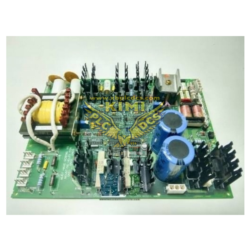
GE DS200DTBDG1 Mark V RST High-Density Signal Termination Board
Product Brief Description
The DS200DTBDG1 is a high-density multi-signal termination board developed by General Electric (GE) for the classic Speedtronic Mark V gas turbine control system, manufactured at GE Fanuc's US industrial production base. As an upgraded high-capacity signal transfer component in the Mark V DS200 series RST system architecture, it undertakes centralized wiring expansion of massive analog and digital mixed signals between the core main control boards and on-site field devices. It supports the full signal conditioning workflow for all types of gas turbine operating parameters, making it one of the most widely deployed high-capacity termination components in global in-service Mark V gas turbine systems.

Core Technical Specifications
- Manufacturer: GE (General Electric) Boards&Turbine Control, original US industrial-grade production standard
- Product Category: Mark V DS200 series high-density RST mixed signal termination board, belonging to the core field wiring supporting component of the Mark V system
- Physical Parameters: Net weight about 1.2kg, industrial multi-layer PCB with anti-corrosion and anti-aging coating, compliant with power plant level anti-vibration and anti-electromagnetic interference standards
- Wiring Capacity: Equipped with 2 independent high-density terminal blocks, supporting access of up to 214 signal wires, meeting the centralized wiring demands of massive field signals in large gas turbine control systems
- Interface Definition: Integrated with multiple dedicated 34-pin system connectors, seamlessly interconnected with TCQA analog I/O board, STCA main logic board and TCQC generator signal processing board in the three redundant cores R1/R2/R3
- Signal Compatibility: Natively supports mixed access of LVDT position signals, servo valve control outputs, thermocouple temperature inputs, 4-20mA analog I/O, vibration sensor signals, pulse speed inputs and digital switch signals
- Operating Environment: -20°C to +70°C working temperature range, 0-95% non-condensing relative humidity, fully meeting power plant industrial EMC anti-interference standards
Key Core Functions
- Ultra-High-Density Centralized Signal Expansion: This board integrates 214 signal wiring terminals, which can centrally undertake the wiring transfer function of almost all non-power type field signals of the gas turbine on a single board. Its signal carrying capacity is 2 times higher than that of ordinary termination boards, effectively saving more than 50% of the control cabinet wiring space and greatly simplifying the complexity of on-site engineering wiring
- Full-Process Signal Preprocessing: Built-in multi-type signal dedicated conditioning circuits on the board, which can perform filtering, surge suppression and signal pre-scaling processing on raw signals collected from field terminals, and then transmit the conditioned standardized signals to the TCQA main control board. This reduces the processing load of the main control board and effectively improves the anti-interference performance of the whole signal link
- Built-in Massive Test Points for Quick Troubleshooting: A large number of standardized ID-marked test points are reserved on the board, maintenance personnel can directly complete signal measurement and status verification on the board surface without disassembling any wiring, which helps to quickly locate abnormal signal points and greatly shorten the system fault downtime
- Flexible Configuration Capability: Multiple configurable hardware jumpers are reserved on the board, which can quickly adjust signal channel attributes and working modes on site according to different project requirements, no need to modify the overall system hardware configuration, making it highly adaptable to various gas turbine renovation and expansion scenarios
Redundant Data Synchronization Support: Through the 3PL dedicated data bus connector, it transmits the preprocessed signals to the STCA main logic board; through the JE dedicated connector, it realizes bidirectional signal transmission with the TCQC generator signal board, ensuring the signal data consistency in the Mark V triple-redundancy control architecture
Typical Application Scenarios
- GE 9E/9F series heavy-duty gas turbine Mark V control systems for large combined cycle power plants
- Spare parts replacement and signal system capacity expansion projects of in-service Mark V systems in large-scale petrochemical refinery captive power plants
- Massive signal centralized wiring supporting for large centrifugal compressor control systems of natural gas long-distance transmission trunk lines and LNG receiving stations
- Auxiliary gas turbine and large boiler system transformation scenarios in large metallurgical steel plants and super-large industrial central heating islands
Installation and Maintenance Guidelines
- Strictly implement anti-static protection before installation: operators must wear reliably grounded anti-static wrist straps to avoid static electricity damaging the precision signal preprocessing components on the board
- Carefully record the ID mark of each ribbon cable connector before dismantling the old board, and install it according to the original mark during reinstallation. Wrong wiring of the multi-group 34-pin connectors will cause signal transmission failure, and even lead to gas turbine signal processing logic errors
- Confirm that all on-board configurable jumpers are correctly set before powering on, and then perform full-point signal loop test through the Mark V system built-in diagnostic function after the hardware wiring is completed
- Regularly check the tightness of wiring terminals and the cleaning status of test points during daily operation, and clean the dust accumulated on the board surface every 2 years, which can effectively extend the service life of this legacy high-density termination board to more than 20 years
Market and Supply Status
Although GE has officially discontinued mass production of this Mark V series high-density termination board, multiple professional industrial DCS spare parts suppliers in Xiamen and Zhangzhou, Fujian still have sufficient spot stocks of original unused and fully refurbished units that have undergone full signal loop testing. The current reference market price is about 9998 CNY, which can be delivered quickly within 1-3 working days, fully meeting the critical spare parts replacement demand of global in-service large-scale Mark V gas turbine control systems.
Frequently Asked Questions
Q: What is the core advantage of this board compared with ordinary Mark V termination boards?
A: Its maximum characteristic is ultra-high signal density, which supports access of up to 214 signal wires on a single board. The signal carrying capacity is far higher than that of ordinary termination boards, which can greatly reduce the total number of boards installed in the control cabinet, simplify the system wiring structure, and reduce the types and quantity of spare parts that the factory needs to store.
Q: Can this board be directly compatible with GE Mark VI system without modification?
A: No, this product is a dedicated high-density signal termination component specially developed for the Mark V system. Its hardware interface definition, signal wiring rules and bus communication logic do not match the newer Mark VI/Mark VIe system, and cannot be directly applied without complete customized hardware modification and system adaptation.
Q: What is the correct operation procedure for using the on-board test points for troubleshooting?
A: First confirm that the board is in normal operating state, refer to the official manual to find the corresponding test point ID of the target circuit, use a calibrated multimeter probe to stably contact the corresponding test point, compare the measured value with the standard reference value given in the manual, so that you can quickly judge whether the signal loop is abnormal. The whole operation must be completed by professionally trained maintenance personnel to avoid short-circuiting adjacent test points and damaging the board.