

News
Featured


Contact Us
Contact: POWER DUKE
Phone: +86 18059884790
E-mail: plc66@qq.com
Add: fujian xiamen
- Warehouse: Spot
- Warranty: 365 days
- Quality: Original module
- Condition: New
- Shipping method: Courier delivery
- Contact person: LI MING
- Contact number: +86 18059884790
- WeChat:18059884790
- E-mail: plc66@qq.com
GE Vernova MVTT14B1BA0772C Static Time Delay Relay Document
1. Product Description
MVTT14B1BA0772C belongs to GE Vernova MVTT14 series solid-state time delay relay, originally Alstom legacy product for power plant substation protection logic control schemes. The model code breakdown: MVTT14 = Delay-on-Pickup static timer base unit; B = Standard housing; 1 = Single-pole double throw SPDT contact; BA = Control voltage specification; 0772C = Full factory configuration code including time range, contact rating and auxiliary features.
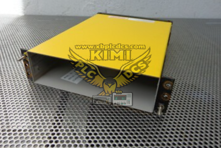
This is a thumbwheel-set electronic timing relay without mechanical clockwork, designed to add definite time coordination delays for overcurrent, earth fault, breaker failure and flame protection interlock circuits. It supports multi-stage adjustable timing ranges, with built-in non-resettable trip LED indicator for fault record retention.
Core electrical specifications:
- Timing range: 1s ~ 1000s continuous adjustable by thumbwheel in 1s increments
- Contact rating: SPDT, 5A continuous AC/DC resistive, 1250VA AC breaking capacity
- Dielectric withstand: 2kV 1min between terminals & earth, compliant IEC 60255-5
- Operating temperature: -10℃ ~ +70℃, conformal coated PCB for dust & humidity resistance
- Mechanical life: 100,000 unloaded operations; 10,000 full-load switching cycles
- Widely used in gas/steam turbine control cabinets, MCC panels and medium voltage switchgear protection logic racks.
2. Core Product Functions
- Delay-On-Pickup Timing Logic When the control input energizes, the relay starts countdown; contact state switches only after the preset time elapses. Perfect for protection coordination delay to avoid instantaneous nuisance tripping.
- Thumbwheel Precision Time Setting Digital thumbwheel dials provide accurate 1-second step adjustment from 1 to 1000 seconds, no analog potentiometer drift issues, stable long-term timing accuracy.
- Latching Trip Indicator LED Front panel red LED latches once timing completes and contact operates; manual reset required to clear indication, convenient for post-fault maintenance troubleshooting.
- Isolated SPDT Dry Contact Output Independent changeover contacts to drive breaker trip coils, alarm annunciators, DCS status signals or secondary protection relay input circuits, fully isolated from control supply.
- Anti-Race Hardwired Logic Stabilization Eliminates signal race conditions in complex interlock circuits (flame loss trip, breaker failure protection, motor startup delay).
- Wide Compatibility With Protection Relays Matches GE Multilin, Alstom legacy protection relays, flame scanner modules and turbine Mark VI control rack logic circuits for graded protection coordination.
- Harsh Industrial Cabinet Adaptability Compact DIN rail mount housing, anti-corrosion PCB coating, immunity to EMI from variable frequency drives and high-current switchgear.
- Low Power Static Circuit Design Solid-state electronic timing circuit consumes minimal standby power, no mechanical coil wear compared to traditional mechanical timing relays.
3. Typical Application Scenarios
- Thermal Power Plant Turbine Control Cabinets Flame loss protection delay for gas/steam turbine burner flame scanners, delay fuel trip signal to avoid transient flame flicker false shutdown.
- Medium-Voltage Substation Feeder Protection Overcurrent backup protection coordination delay, realize time grading between upstream main breaker and downstream feeder relays.
- Motor Control Center (MCC) Panels Motor startup cold-load pickup delay, prevent instantaneous overload trip during large motor inrush current.
- Oil & Gas Refinery Compressor Turbines Breaker failure protection timing, send backup trip command if primary breaker fails to open within preset delay.
- Chemical Plant Furnace & Incinerator Safety Logic Delayed ventilation fan interlock, purge chamber delay before igniting process burners to eliminate residual hazardous gas.
- Water Treatment Plant Pump Control Panels Sequential pump startup delay to avoid simultaneous large current surge on distribution transformers.
- Mining Metallurgy Substation Switchgear Earth fault graded protection delay, selective fault isolation for underground mining power distribution feeders.
4. Common Faults & Troubleshooting Issues
4.1 Relay Never Times Out, No Contact Switching After Input Energized
Causes: Incorrect control supply voltage mismatch; open-circuit input wiring; damaged internal timing chip; thumbwheel dial misaligned or broken. Solution: Measure coil control voltage against nameplate rating; check input terminal continuity; re-calibrate thumbwheel setting; replace MVTT14B1BA0772C if internal circuit failure confirmed.
4.2 Timing Duration Drifts, Actual Delay Far Shorter/Longer Than Set Value
Causes: Cabinet ambient temperature over 70℃; dust conductive deposits on PCB timing circuit; aging timing capacitor. Solution: Improve cabinet cooling ventilation; clean internal PCB dust; replace relay if timing deviation exceeds allowable tolerance.
4.3 Latching Trip LED Cannot Be Reset Manually
Causes: Mechanical reset button stuck; internal LED latch circuit damaged; continuous energized input signal holding latch state. Solution: Confirm input control signal de-energized; clean or repair front reset pushbutton; power cycle relay to reset internal logic latch.
4.4 Output Contact Chattering, Unstable Load Actuation
Causes: Loose DIN rail mounting causing vibration; strong EMI interference from adjacent high-power contactors; loose wiring terminals. Solution: Secure relay DIN rail mounting; route control wiring with shielded twisted cables; re-tighten all terminal block connections.
4.5 Contact Cannot Drive Trip Coil Load After Long-Term Operation
Causes: Contact burnout by inductive trip coil without freewheeling diode; load current exceeds rated 5A contact capacity; contact surface oxidation. Solution: Add auxiliary interposing relay for heavy inductive loads; install surge suppression diodes across trip coil terminals; replace timing relay if contacts are permanently degraded.
4.6 Intermittent Timing Failure Under High Humidity Cabinet Environment
Causes: PCB conformal coating peeling, humid air causing partial micro-short on timing circuit traces. Solution: Schedule cabinet dehumidification maintenance; reapply industrial high-temperature conformal coating; replace unit if corrosion leads to permanent circuit damage.