

News
Featured
Contact Us
Contact: POWER DUKE
Phone: +86 18059884790
E-mail: plc66@qq.com
Add: fujian xiamen
- Warehouse: Spot
- Warranty: 365 days
- Quality: Original module
- Condition: New
- Shipping method: Courier delivery
- Contact person: LI MING
- Contact number: +86 18059884790
- WeChat:18059884790
- E-mail: plc66@qq.com
GE DS200UDSAG1ADE Mark V DS Auxiliary Signal Board Document
1. Product Description
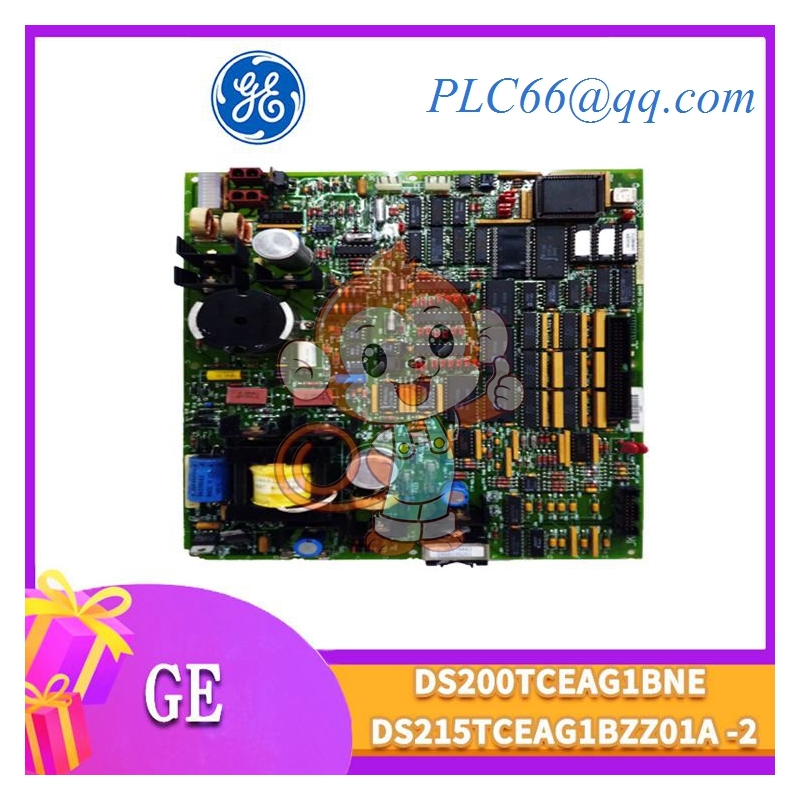
DS200UDSAG1ADE is a core auxiliary signal interface circuit board designed for GE Speedtronic Mark V gas & steam turbine control systems, belonging to the DS series signal conditioning module family. It is a plug-in rack-mounted PCB board installed inside the Mark V turbine control cabinet, acting as a signal bridge between field auxiliary sensors, local interlock switches and the main turbine control CPU board.
This board processes multiple types of discrete digital input/output signals, low-level analog auxiliary signals and fault interlock signals, with built-in surge suppression and optocoupler isolation circuits to resist high electromagnetic interference from turbine high-voltage power equipment. The model DS200UDSAG1ADE is a full standard version with complete terminal pin definitions, compatible with all standard Mark V turbine rack chassis, supporting hot-swap maintenance under controlled power-off conditions.
Electrical specifications: Powered by 24VDC control power from the rack backplane, operating temperature range 0°C ~ +60°C, PCB conformal coating for dust and humidity resistance, fully compliant with GE power generation control equipment industrial standards.
2. Core Product Functions
- Discrete Digital Signal Isolation & Conversion: Equipped with multi-channel optocoupler isolation circuits to convert field dry contact switch signals into digital logic signals recognizable by the Mark V main controller; isolates field high-interference circuits to protect the main CPU.
- Auxiliary Analog Signal Conditioning: Processes low-level auxiliary analog signals from lube oil pressure, bearing temperature, seal gas pressure and other auxiliary turbine sensors, filters signal noise and transmits standardized analog values to the control bus.
- Turbine Auxiliary Interlock Logic: Collects critical interlock signals including lube oil pump run status, fire suppression valve position, exhaust temperature alarm, emergency stop auxiliary contacts; outputs interlock trip signals to the main protection board when abnormal conditions occur.
- Surge & Transient Voltage Protection: Built-in TVS diodes and RC absorption circuits on all external signal terminals, suppress voltage spikes generated by turbine solenoid valves and contactors to avoid PCB circuit burnout.
- On-Board Fault Indication & Diagnostic Feedback: Integrated LED status indicators for each signal channel to display channel open/short circuit and power supply faults; transmits channel fault codes to the Mark V operator HMI for real-time alarm display.
- Rack Backplane Bus Communication: Communicates bidirectionally with the Mark V main control board via the rack backplane, uploading all auxiliary measurement and interlock status data, receiving control output commands from the CPU.
- Solenoid Valve Drive Auxiliary Output: Provides low-power buffered digital output signals to drive small auxiliary solenoid valves, indicator lights and local alarm buzzers on the turbine unit.
- Conformal Coated Anti-Corrosion Design: The entire PCB surface is coated with insulating conformal coating, adapting to high-temperature, high-dust and slight humidity environments inside power plant turbine cabinets.
3. Typical Application Scenarios
- Combined Cycle Power Plant Gas Turbine Control: GE Frame 5, Frame 6, Frame 7, Frame 9 gas turbine Mark V control cabinet auxiliary signal collection and interlock protection.
- Steam Turbine Governing & Auxiliary Control: Monitor steam turbine lube oil system, cooling water system, vacuum system auxiliary switches and sensor signals.
- Cogeneration Industrial Power Units: Small industrial gas turbine units for factory self-generation, auxiliary safety interlock signal processing.
- Oil & Gas On-Site Turbine Compressors: Gas turbine driven pipeline compressors, process auxiliary valve position and pressure signal acquisition.
- Thermal Power Plant Auxiliary Boiler Turbines: Supervise auxiliary pump, fan and valve interlock signals of boiler auxiliary turbine equipment.
- Independent Power Plant Turbine Safety Systems: Collect emergency stop, fire protection and equipment fault discrete signals to form multi-layer safety interlock logic.
4. Common Faults & Troubleshooting Issues
4.1 Single Channel Signal Loss, HMI Shows Bad Point
Causes: Damaged optocoupler chip on PCB, loose terminal wiring, open field sensor/switch circuit, terminal block corrosion. Solution: Check channel LED indicator status; test field wiring continuity; clean corroded terminal contacts; replace the optocoupler component or the whole DS200UDSAG1ADE board if chip breakdown occurs.
4.2 Board Not Detected by Mark V Main Controller
Causes: Poor contact between board edge connector and rack backplane, backplane 24VDC power supply undervoltage, broken bus communication circuit on PCB, severe dust accumulation on gold fingers. Solution: Power off the rack, pull out the board and clean edge connector gold fingers; inspect rack power supply voltage; reinsert the board fully and lock the fixing latches.
4.3 False Auxiliary Interlock Trip Without Actual Equipment Fault
Causes: Transient voltage surge damaging signal isolation circuit, unshielded field cables causing EMI interference, loose wiring generating intermittent signal disconnection. Solution: Add shield grounding for all field signal cables; inspect surge protection components on PCB; re-tighten all terminal wiring terminals.
4.4 PCB Overheating, Intermittent Signal Fluctuation
Causes: Cabinet cooling fan failure, dust buildup covering PCB heat-generating components, long-term full-load multi-channel signal operation, cabinet ambient temperature exceeding 60°C. Solution: Clean dust from the board surface and cabinet air ducts; replace invalid cooling fans; reduce long-term continuous signal load of the board.
4.5 Solenoid Auxiliary Output Fails to Actuate Load
Causes: Damaged output buffer transistor on the board, short-circuit of external solenoid load exceeding board current limit, broken output terminal wiring. Solution: Disconnect external solenoid load to isolate board fault; test output circuit transistor performance; replace the signal board if internal drive circuit burnout.
4.6 Conformal Coating Degradation & PCB Short Circuit Risk
Causes: Long-term exposure to high temperature and humid cabinet environment, aging and peeling of insulating coating, conductive dust deposition between PCB traces. Solution: Regularly clean the board surface dust; re-spray conformal coating during overhaul; replace the board if coating peeling leads to trace short circuit.