

News
Featured

Contact Us
Contact: POWER DUKE
Phone: +86 18059884790
E-mail: plc66@qq.com
Add: fujian xiamen
- Warehouse: Spot
- Warranty: 365 days
- Quality: Original module
- Condition: New
- Shipping method: Courier delivery
- Contact person: LI MING
- Contact number: +86 18059884790
- WeChat:18059884790
- E-mail: plc66@qq.com
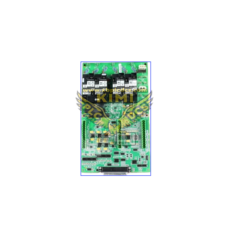
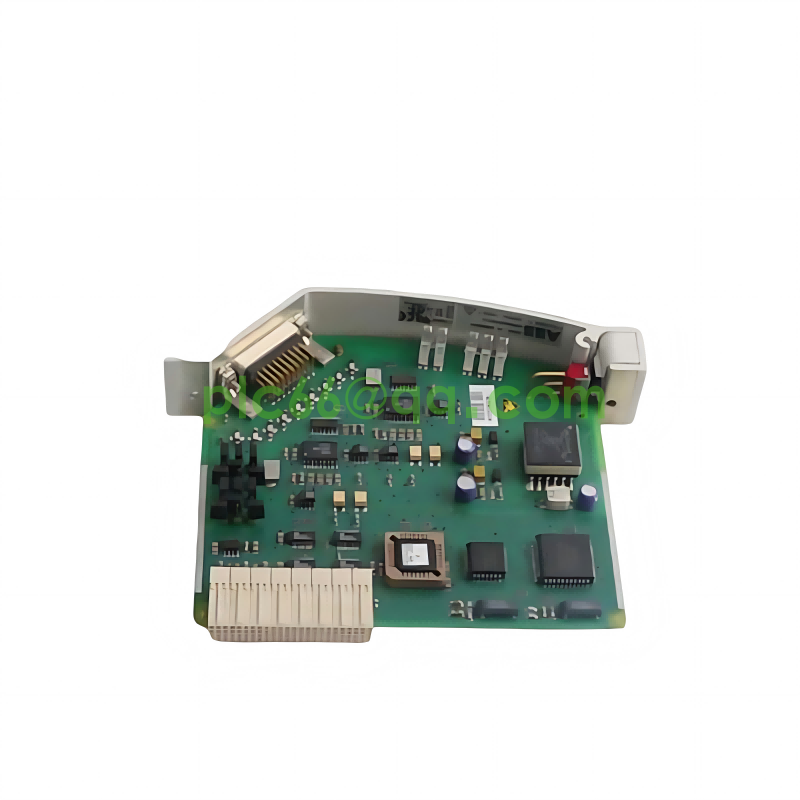
GE IS200EGDMH1AFF Exciter Gate Driver & Field Ground Detection Module (Mark VIe System)
1. Product Description
The IS200EGDMH1AFF is a plug-in industrial PCB module manufactured by GE for the Mark VIe distributed turbine control system, also known as Exciter Gate Driver Module (EGDM) with integrated exciter field ground fault detection function. It adopts conformal coated PCB for dust, moisture and chemical corrosion resistance, standard rack-mounted form factor compatible with EX2100 excitation control racks. Powered by 28–32 VDC control supply, it provides galvanic isolation (2500V RMS) between low-voltage control logic and high-power excitation circuits to suppress electrical noise interference. The module supports simplex, duplex and triple modular redundancy (TMR) configurations, complies with SIL2/SIL3 functional safety standards for power generation critical equipment, and communicates with system DSPX, EXAM main control boards via backplane digital bus and fiber optic differential signals.
2. Core Product Functions
- IGBT Exciter Gate Drive Control: Output ±15V high-speed gate drive signals to power semiconductor IGBTs of generator excitation rectifiers, precisely regulating excitation field voltage and current to stabilize synchronous generator terminal voltage under dynamic load fluctuation.
- AC/DC Exciter Field Ground Fault Detection: Built-in leakage current detection circuit monitors both AC and DC sides of exciter field winding; rapidly identifies insulation degradation and ground short-circuit faults, transmits fault codes to the main control unit for protection interlock trigger.
- Multi-Layer Circuit Protection Logic: Integrates overcurrent, overvoltage, overtemperature and transient surge suppression circuits; automatically blocks gate drive output when abnormal parameters are detected to prevent damage to excitation power units and generator rotors.
- Redundant System Signal Voting Support: Compatible with triple redundant TMR control architecture; realizes fault signal cross-voting among multiple EGDM modules to avoid single-point control failure and ensure uninterrupted generator operation.
- Real-Time Operational Data Diagnostics: Onboard signal sampling circuit collects excitation current, field voltage, module temperature and fault status data; local LED indicators and system HMI provide real-time diagnostic information for rapid maintenance positioning.
- Isolated Fiber Optic Communication Interface: Uses fiber optic differential signal transmission to isolate high-power circuit interference, reliably receive excitation setpoint commands from Mark VIe main control boards and upload field monitoring data back to the system controller.
3. Typical Application Scenarios
- Gas turbine, steam turbine and hydroelectric generator excitation control systems equipped with GE Mark VIe / EX2100 control racks
- Coal-fired, natural gas combined-cycle power plants, nuclear auxiliary power generation units requiring high-reliability excitation regulation
- Industrial self-owned power stations, large chemical plant backup generator sets and heavy industry synchronous generator control systems
- Wind farm synchronous generator excitation control and hydroelectric power station turbine governor matching excitation equipment
- Power equipment testing laboratories, excitation system simulation and performance verification test benches
- Maintenance spare replacement for aging EGDM modules in existing GE Mark VIe turbine control cabinets
4. Common Issues & Troubleshooting
Issue 1: System reports exciter field ground fault alarm with no actual winding insulation damage
Root Causes: Loose backplane connector pins; dust accumulation on PCB leakage detection circuit; interference from adjacent high-power cables; module internal sampling circuit drift. Solutions: Power off the rack, clean PCB dust and re-seat the module tightly; separate power cables from control signal wiring; calibrate ground fault detection threshold via control HMI; replace module if internal sampling circuit fails.
Issue 2: Generator voltage unstable, excitation current fluctuating abnormally
Root Causes: Damaged fiber optic communication cable causing lost excitation setpoint signals; aging gate drive output circuit with inconsistent drive amplitude; poor contact of power terminal connectors generating heat drift. Solutions: Inspect and replace fiber optic links; measure gate drive output voltage waveform; tighten all power and signal terminal screws; perform module firmware upgrade if supported.
Issue 3: Module overtemperature alarm after long continuous operation
Root Causes: Blocked rack cooling air duct; thick dust coverage on PCB heat dissipation components; rack ambient temperature exceeding 70°C upper limit; adjacent power modules radiating excess heat. Solutions: Clean rack ventilation filters and PCB dust; adjust cabinet air conditioning to maintain operating temperature between -20°C ~ +60°C; install heat insulation baffles between high-power modules.
Issue 4: TMR redundant system triggers single module fault isolation alarm
Root Causes: Inconsistent firmware versions among three redundant EGDM modules; uneven backplane contact resistance leading to signal voting mismatch; damaged internal signal processing chip. Solutions: Unify firmware version for all redundant modules; extract and clean backplane gold-plated connectors; replace faulty module if internal chip damage is confirmed via diagnostic log.
Issue 5: No gate drive output, generator excitation fails to build up voltage
Root Causes: 28VDC control power supply loss; module overcurrent protection latch triggered; broken gate drive output wiring to IGBT power unit; internal power circuit fuse blown. Solutions: Check rack control power supply voltage; clear protection fault latch through system reset; test continuity of gate drive wiring; replace module if internal fuse or power circuit is damaged.